
Operations & visualization
What is a digital twin? Meaning, types, and how plants apply it
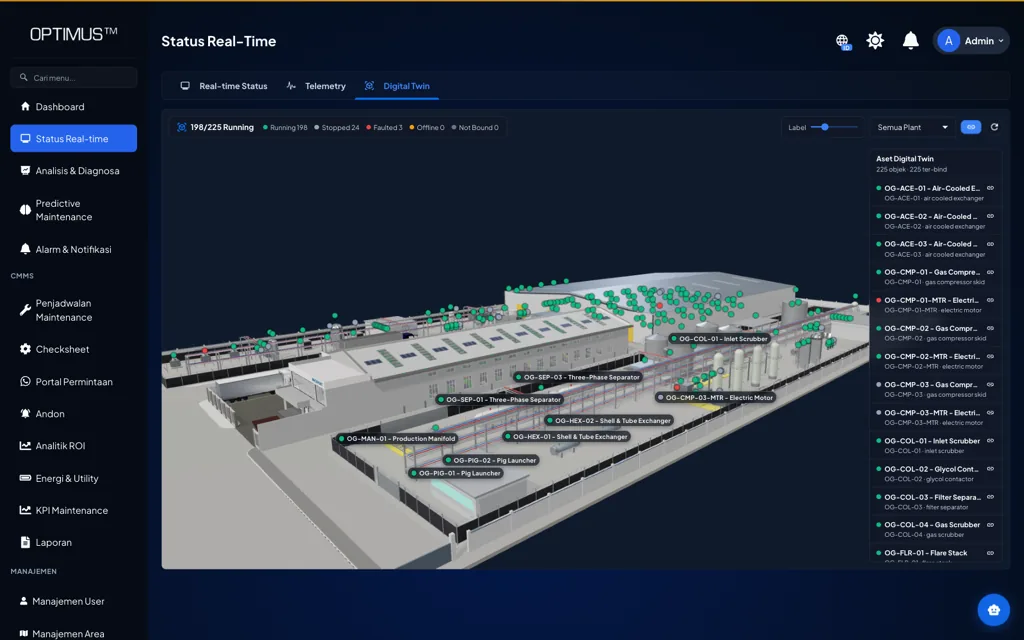
On screen, the 3D model of the plant looks convincing: every machine in its place, complete with colors and labels. The question is whether the model knows that compressor number two has just tripped. A model only earns the name digital twin when it and the plant it represents stay connected by data.
Key takeaways
- A digital twin is a digital representation of an asset or process that stays in sync with its physical condition through a flow of data, not merely a 3D model.
- Kritzinger et al. distinguish a digital model, a digital shadow, and a digital twin by the direction of the data flow and whether that flow is automatic or manual.
- The foundation is not graphics but a clean asset hierarchy, live data integration from PLCs, sensors, and meters, and one source of truth for asset data.
- Many systems marketed as digital twins are in fact digital shadows, and for most plants that scope is often the right one.
What a digital twin is
A digital twin is a digital representation of a physical object, such as a machine, a production line, or one area of a plant, that is continuously updated by data from that object. The key word is "updated". When a pump bearing starts vibrating harder, the vibration value on the model changes with it. When an injection molding machine stops on an alarm, its status on screen changes too.
The idea is usually credited to Michael Grieves, who introduced it in the context of product lifecycle management (PLM). In his account, a digital twin has three parts: the physical product in real space, the virtual product in virtual space, and the connections of data and information that tie the two together[1]. The third part is the one most often forgotten. A virtual product without a data connection is only a drawing or an engineering model, however good it looks.
The term is now used very widely, and its meaning is not always the same from one author to the next. A systematic literature review by Jones et al. notes the variety of definitions in circulation and sets out the common characteristics of a digital twin, among them a physical entity, a virtual entity, and connections from physical to virtual and from virtual to physical[2]. For practitioners in a plant, this variety has a simple consequence: when someone offers a "digital twin", the first questions to ask are what data flows, in which direction, and how often.
Digital model, digital shadow, and digital twin
The classification most often cited to answer those questions comes from Kritzinger et al. They distinguish three levels of integration based on the data flow between the physical object and the digital object[3]. The distinction does not lie in the quality of the graphics or the sophistication of the algorithms, but in whether data moves automatically or manually, and in which direction.
| Level | Physical to digital | Digital to physical | Example in a plant |
|---|---|---|---|
| Digital model | Manual | Manual | A CAD layout of a line that an engineer updates each time a new machine arrives; a simulation model fed with data from a spreadsheet |
| Digital shadow | Automatic | Manual | A 3D plant model that shows status and sensor values live, while actions are still decided and carried out by people |
| Digital twin | Automatic | Automatic | A model that receives process data and sends setpoint or schedule changes back to the control system without a manual step |
According to Kritzinger et al., in a digital twin a change in the physical object is automatically reflected in the digital object, and vice versa [3].
In a digital model, there is no automatic data exchange at all. The model can be very detailed, but it is only as good as the last update someone made. A digital shadow adds an automatic flow from physical to digital: machine status, motor current, or bearing temperature arrives in the model on its own. Decisions taken from that model are still carried back to the shop floor by people, for example through a work order or an instruction to an operator. Only at the digital twin level does the return flow from digital to physical also run automatically.
The classification is useful because it is honest. In their review, Kritzinger et al. found that many publications using the digital twin label actually describe a digital model or a digital shadow[3]. The same pattern is easy to find in the industrial software market. That does not make those systems useless. It means buyers and users need to know exactly which level they are talking about.
The ISO 23247 framework for manufacturing
For manufacturing, ISO publishes the ISO 23247 series on a digital twin framework, and its first part sets out the overview and general principles[4]. The standard treats a digital twin for manufacturing as a fit for purpose digital representation of an observable manufacturing element, with synchronization between that element and its digital representation.
The scope of an observable manufacturing element is broad, covering among others equipment, material, personnel, processes, facilities, products, and the environment[4]. In other words, a digital twin does not have to be a model of the whole plant. One compressor, one filling line, or one drying process can be the subject of its own digital twin, provided it is clear which element is being observed and for what purpose.
The phrase fit for purpose is the most practical lesson in the standard. A digital twin is not judged by how completely it imitates reality, but by whether its representation is enough for the decision it is meant to support. A twin for monitoring pump status in the utility area needs different data and a different level of detail from a twin for testing the PLC logic of a robot palletizer before it is installed.
What a plant needs to build a digital twin
Discussions of digital twins often start with the visuals, yet the parts that matter most are the ones nobody sees. Four foundations need to be in place, and three of them are about data, not graphics.
A clean asset hierarchy
Every object in the model has to point to one asset with a clear identity. That requires an orderly asset hierarchy: plant, area, line or system, asset, then component or measurement point. If the same pump is recorded as "P-101" in the CMMS, "Transfer Pump 1" in SCADA, and "Pump_A" in the 3D model file, synchronization will keep breaking. Agreeing on asset codes and their structure sounds administrative, but this is the work that lets data from different systems meet on one object.
Live data integration
Live data usually comes from three sources: PLCs and control systems (running, stopped, and alarm status, production counters), condition sensors (vibration, temperature, pressure), and energy meters. Common protocols on the shop floor include Modbus, OPC UA, and MQTT, with gateways bridging older equipment that has no modern network interface.
- 01Physical asset
- 02PLC, sensors, meters
- 03Gateway
- 04Asset database
- 052D or 3D model
- 06Decision and action
One thing often overlooked is how fresh the displayed data is. Jones et al. call the frequency of synchronization between the physical and virtual entities the twinning rate[2]. In practice, what users experience is data age: the gap between the moment a value is measured and the moment it appears on screen.
Maximum data age (rough estimate)
Max. data age ≈ sampling interval + transmission and processing latency + display refresh interval
All terms are in the same unit of time. The maximum data age has to be shorter than the time available for the decision it is meant to support.
The figures below are illustrative. A gateway reads a compressor status every 10 seconds, transmission and processing take 2 seconds, and the model display refreshes every 5 seconds. The worst-case data age is 10 + 2 + 5 = 17 seconds, enough to monitor the status of the utility area from a control room. If the same data is sent only every 15 minutes (900 seconds), its age can reach 900 + 2 + 5 = 907 seconds, just over 15 minutes. A compressor that trips will not show up on the model in time to be useful to the night shift operator. Note, too, that a data age of well under a minute still does not turn the model into a protection system. Protecting the machine remains the job of the PLC and the interlocks in the field.
A 2D or 3D model at a sensible level of detail
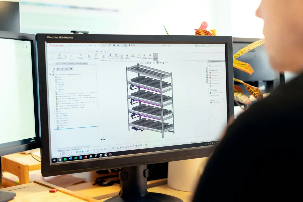
The visual model does not have to be photorealistic. Jones et al. use the term fidelity to describe how many parameters are exchanged between the physical and virtual entities, how accurate those parameters are, and at what level of abstraction[2]. For an operational twin in a plant, a sensible level of detail usually means that every asset can be recognized by its shape and position, while bolts, cables, and small-bore piping can be simplified. A highly detailed engineering CAD model is often too heavy to open in a browser or on a control room screen, and has to be simplified first.
For many purposes, a 2D floor plan is enough. A shop floor layout with a status symbol for each machine can answer the same questions as a 3D model, at a much lower cost to build and maintain. A 3D model earns its keep when vertical position and space really matter, for example in a process plant with multi-level piping or in a warehouse with high racking.
One source of truth for asset data
The fourth foundation is a single source of truth for asset data: specifications, location, repair history, and alarm limits. The 3D model should not keep its own copy of this data, but read it from the system that serves as the reference, such as the asset register in the CMMS. Otherwise, within a few months there will be two versions of the truth, the data in the model and the data in the maintenance system, and nobody will be sure which one is right.
What a digital twin is used for on the shop floor
The review by Tao et al. summarizes industrial applications of digital twins, among them product design, production, and prognostics and health management (PHM)[5]. At plant level, the most common uses fall into the following groups.
- Status visualization. Every asset in an area is visible at once, with its running, stopped, or fault status. A shift supervisor can read the state of the plant in a few seconds without opening a stack of HMI screens.
- Locating assets in alarm. An alarm in a text list only gives an asset code. On the model, the alarm appears at its physical location, so even a newly hired technician knows which building and which floor to head for.
- Context for maintenance. By selecting one asset, a technician sees its active alarms, open work orders, running hours, and condition trends in one place before heading out to the floor.
- What-if analysis. A sufficiently complete model can be used to test scenarios before they are tried on the shop floor, for example the effect of shutting down one compressor on compressed air network pressure, or a change to a line layout.
- Virtual commissioning. PLC logic and machine sequences are tested against a virtual model before the physical machine is installed, so some programming errors are found at the engineer's desk rather than during start-up.
The first three uses are already within reach of a digital shadow. The last two need a behavioral model, not just a geometric one: the model has to know how pressure falls when a compressor stops, or how a conveyor responds to a sensor signal. Building a behavioral model like that is an engineering job in its own right, and its cost has to be weighed against the value of the decisions it will support.
Limits worth understanding
If the Kritzinger et al. classification is applied strictly[3], many systems marketed as digital twins are in fact digital shadows: data flows automatically from the machine to the model, but not the other way. Admitting this need not be seen as a shortcoming.
For many plants, a digital shadow is exactly the right scope. Sending automatic commands from the model to the machine makes the model part of the control system, with all that follows: hazard analysis, validation, management of change, and the question of who is accountable if a command is wrong. In most plants, the decision to stop a machine or change a setpoint is safer left with operators and engineers, with the model serving as an aid to seeing. An automatic return flow makes sense for limited, well-defined cases, not as a starting point.
Another limit comes from the data itself. A model is only as smart as the data that goes into it. An uncalibrated sensor, a mis-mapped PLC tag, or a gateway that quietly stops sending will produce a model that looks convincing but is wrong. A good system therefore also shows when data was last received and flags assets whose data has dropped out, instead of continuing to display the last value as if it were still current.
Steps to apply a digital twin in a plant
- Define the decision you want to support. For example, "the shift supervisor must know within one minute which assets in the utility area have stopped". This goal determines the data, the level of model detail, and the data age required.
- Choose a small initial scope. Start with one area or one system that has critical assets and data sources already available, not with the whole plant.
- Clean up the asset hierarchy and codes. Agree on one code for each asset and make sure the same code is used in the CMMS, in SCADA, and in the model.
- Map the data sources. List the PLC tags, sensors, and meters for each asset, with their protocol, sampling interval, and units. Flag assets that have no data yet.
- Build the model with just enough detail. Use a 2D floor plan or a simplified 3D model, then bind each object to its asset code.
- Test against real conditions. Stop one machine in a planned way or trigger a test alarm, then check that the model shows the change correctly and within the expected time.
- Connect it to the workflow. Make sure what is seen on the model leads to action: an alarm becomes a work order, and the work order can be opened from the asset object.
- Expand step by step. Add the next area once the first model is genuinely used in daily meetings and shift handovers.
Common mistakes
- Starting with the graphics. The budget goes on a detailed 3D model while data integration is postponed. The result is a beautiful but static model.
- Ignoring data quality. A wrong value looks more convincing when it is shown on a 3D model. Tag validation and sensor calibration still have to be done.
- Keeping duplicate asset data. A model that keeps its own copy of specifications and status will drift away from the CMMS within months.
- Promising automatic control too early. A return flow to the machine demands serious safety review and validation. Making it an initial requirement often means the project never finishes.
- Not naming an owner. Layouts change, machines are moved, and sensors are replaced. Without someone responsible for updating the model and its mappings, the accuracy of the digital twin declines month after month.
Conclusion
A digital twin is a digital representation kept in sync with its physical object, and that synchronization is what sets it apart from an ordinary 3D model. The Kritzinger et al. classification offers an honest vocabulary for talking about it: a digital model, a digital shadow, and a digital twin are distinguished by the direction and automation of the data flow, not by the quality of the graphics[3].
For most plants, the realistic starting point is a reliable digital shadow for one area: a clean asset hierarchy, live data that is fresh enough, a model with just enough detail, and one source of truth for asset data. Once that foundation is running and genuinely used in daily decisions, further uses such as what-if analysis or virtual commissioning can be built on top of it on solid ground.
Frequently asked questions
What is a digital twin?
A digital twin is a digital representation of an asset, process, or plant area that is continuously updated by data from its physical object, such as machine status and sensor values. Without that data connection, the model is only a drawing or an engineering model.
What is the difference between a digital model, a digital shadow, and a digital twin?
In the classification by Kritzinger et al., a digital model has no automatic data flow, a digital shadow receives data automatically from the physical object but actions back are taken manually, and a digital twin has automatic data flow in both directions.
Does a digital twin have to be a 3D model?
No. A 2D floor plan with a status for each machine is often enough. A 3D model is more valuable when position in space really matters, for example in a process plant with multi-level piping.
How is a digital twin different from a simulation?
A simulation runs a model for a given scenario, often with data entered by hand. A digital twin stays connected to its physical object and is updated by live data; simulation can be one of its uses, for example for what-if analysis.
Can a digital twin control machines?
In the Kritzinger et al. classification, a full digital twin does send data back to the physical object automatically. In many plants, control stays with the PLC and the operator for reasons of safety and validation, so the model is used as an aid to seeing and deciding.
References
- [1]Grieves, M. (2014). Digital twin: Manufacturing excellence through virtual factory replication [White paper].
- [2]Jones, D., Snider, C., Nassehi, A., Yon, J., & Hicks, B. (2020). Characterising the Digital Twin: A systematic literature review. CIRP Journal of Manufacturing Science and Technology, 29, 36-52.
- [3]Kritzinger, W., Karner, M., Traar, G., Henjes, J., & Sihn, W. (2018). Digital Twin in manufacturing: A categorical literature review and classification. IFAC-PapersOnLine, 51(11), 1016-1022.
- [4]International Organization for Standardization. (2021). ISO 23247-1:2021, Automation systems and integration: Digital twin framework for manufacturing, Part 1: Overview and general principles. ISO.
- [5]Tao, F., Zhang, H., Liu, A., & Nee, A. Y. C. (2019). Digital twin in industry: State-of-the-art. IEEE Transactions on Industrial Informatics, 15(4), 2405-2415.