
Asset reliability
Why an electric motor runs hot, and what to do about it
The pump motor has tripped three times this week, and each time the operator pressed reset and production carried on. The motor housing feels very hot, but nobody knows whether that heat is normal or the sign of damage in progress. This article covers when a motor counts as too hot, where the heat comes from, and how to check it in the right order.
Key takeaways
- An induction motor always produces heat. What matters is whether its winding temperature stays below the limit of its insulation class, not how hot the frame feels to the hand.
- Insulation life is very sensitive to temperature; a widely used rule of thumb says insulation life roughly halves for every increase of about 10 °C above its limit.
- The causes of an electric motor running hot fall into three groups: electrical (overload, voltage unbalance, voltage too low or too high, single phasing, harmonics, too many starts), mechanical (bearings, misalignment, heavy load), and cooling (fan, dirty fins, high ambient temperature).
- Checks start with safety, then voltage and current on each phase, cooling, and the mechanical side. Resetting the protection again and again, or raising its setting, only postpones the damage.
A hot electric motor: when is it too hot?
This article covers why an electric motor runs hot, specifically the three-phase induction motors that drive pumps, fans, compressors, conveyors, and production machines in factories, not e-bike motors or household appliances. The principles are similar, but the power range, the protection, and the consequences of a stop are very different.
Every motor turns part of its electrical input into heat rather than rotation. Copper losses in the stator and rotor windings, iron core losses, bearing friction, and fan windage all end up as heat that has to be carried away into the surrounding air. A healthy motor reaches a balance: the heat it produces equals the heat it sheds, and its temperature settles at a level the designer has already accounted for.
Trouble starts when that balance shifts: more heat is produced, or less can be shed. The part that suffers most is the stator winding insulation. Bonnett and Soukup place thermal stress among the main stresses that damage stator insulation, alongside electrical, mechanical, and environmental stresses[1]. So the question "my electric motor gets hot quickly, is that dangerous?" is really a question about insulation life.
Normal electric motor temperature and insulation class
There is no single normal temperature that applies to every motor. The upper limit is set by the thermal class of the insulation system, which IEC 60085 designates by a temperature number. The three classes most often found on industrial motors are class 130 (formerly B), 155 (F), and 180 (H), with class temperatures of 130 °C, 155 °C, and 180 °C respectively[2]. Those figures are limits for the hottest part of the insulation, not for the surface of the frame.
IEC 60034-1 then sets how much temperature rise of the winding is allowed above the coolant temperature, with a reference cooling air temperature of no more than 40 °C and an installation altitude of no more than 1,000 m[3]. Temperature rise is expressed in kelvin (K) and, with the resistance method, describes the average winding temperature. The hottest spot inside the winding is always somewhat above that average, so a margin is left for it.
| Thermal class | Class temperature | Temperature rise limit (resistance method) | Margin at 40 °C cooling air |
|---|---|---|---|
| 130 (B) | 130 °C | 80 K | 10 K |
| 155 (F) | 155 °C | 105 K | 10 K |
| 180 (H) | 180 °C | 125 K | 15 K |
Class temperatures from IEC 60085 [2]; temperature rise limits from IEC 60034-1 [3] for most air-cooled motors. Very small motors and other measurement methods have different limits. The last column is a calculation: class temperature minus 40 °C minus the temperature rise limit.
Many industrial motors use class F insulation but are designed so that their temperature rise stays within the class B limit. That difference becomes a thermal reserve: the motor still has room when the ambient is hotter than usual or the load occasionally rises. The motor nameplate states its insulation class, and that is the first piece of data to read before judging whether a motor is too hot.
Winding temperature is not the temperature you touch
The temperature that can be measured in the field without opening the motor is usually the surface temperature of the frame or the bearing housing. Heat flows from the winding through the iron core to the frame, and is then carried away by the fins and the fan airflow, so the frame surface is always cooler than the winding. How much cooler depends on the motor’s design, size, and cooling method. As a result, a frame too hot to touch for more than a second or two does not necessarily mean the winding is over its limit, and a frame that merely feels warm does not guarantee the winding is safe.
That is why a more useful yardstick than an absolute figure is a comparison: this motor’s frame temperature today against its own temperature last week at similar load and ambient, or against its twin doing the same duty. Better still is to record the temperature rise above ambient rather than the absolute temperature, because a pump room in the afternoon can be several degrees hotter than at night.
Electrical causes
Bonnett and Soukup describe the conditions that load stator insulation thermally, among them voltage variation, unbalanced phase voltages, repeated starting and stopping, overload, obstructed ventilation, and high ambient temperature[1]. Most of those causes originate on the electrical side, and all of them come down to the same thing: more current than there should be, or more losses at the same current.
- Overload. The motor draws current above its nameplate rated current because the mechanical load exceeds its rating. Copper losses rise with the square of current, so even a small excess of current adds meaningful heat.
- Voltage unbalance. A small difference between the three phase voltages produces a much larger current unbalance; NEMA MG 1 notes that current unbalance can reach several times the voltage unbalance[4].
- Voltage too low or too high. At low voltage the motor draws more current to deliver the same power. At high voltage the magnetizing current and core losses rise. IEC 60034-1 defines zone A, ±5% voltage and ±2% frequency, as the range for continuous operation; in the wider zone B the motor must still run, but its temperature rise is higher and prolonged operation there is not recommended[3].
- Loss of one phase (single phasing). A blown fuse or a worn contactor contact leaves the motor running on two phases. A motor that is already turning often keeps running, but the current in the remaining phases jumps and the winding is quickly damaged; a motor at standstill will not start. The winding damage pattern from this condition is among those described by Bonnett and Soukup[1].
- Harmonics and drives. A motor run from a variable frequency drive (VFD) receives PWM voltage that adds harmonic losses. At low speed, the shaft-mounted fan slows as well, so cooling drops just when the required torque may still be high.
- Too many starts. Each start draws several times rated current for several seconds, and most of that heat stays in the rotor. NEMA MG 1 limits the successive starting capability of general purpose motors, for example two starts in succession from ambient temperature[4]. IEC 60034-1 also distinguishes duty types, from S1 (continuous) to intermittent duties with repeated starts, and a motor must be selected for its duty type[3].
Calculating voltage unbalance
Voltage unbalance is easy to miss because the panel voltmeter shows only one phase, or because each phase looks "still about 400 V". NEMA MG 1 gives a way to calculate it from the three line-to-line voltages[4].
Voltage unbalance per NEMA MG 1
Unbalance (%) = 100 × maximum deviation from average ÷ average voltage
Average voltage = the average of the three line-to-line voltages (R-S, S-T, T-R), measured at the terminals or panel with the motor under load.
Maximum deviation = the largest difference between any one line-to-line voltage and the average voltage.
The following figures are illustrative. At the panel of a 400 V pump motor, the line-to-line voltages measure 402 V, 396 V, and 387 V. The average is (402 + 396 + 387) ÷ 3 = 1,185 ÷ 3 = 395 V. Each phase deviates from the average by 7 V, 1 V, and 8 V, so the maximum deviation is 8 V. The unbalance is 100 × 8 ÷ 395 = 2.03%. The spread between the highest and lowest phase is only 15 V, yet the result is already past 1%.
NEMA MG 1 gives a derating curve for motors operated at a voltage unbalance above 1%, and does not recommend operation above 5%[4]. In other words, the motor in this example should no longer be loaded fully to its nameplate. The source of unbalance usually lies upstream of the motor: single-phase loads spread unevenly across the distribution panel, loose connections, worn contactor contacts, or a power factor correction capacitor bank with one failed unit.
Mechanical causes
The mechanical side adds heat in two ways: direct friction in the bearings, and extra load that makes the motor draw more current. Both often show up as a motor that runs hot at one end first, not across the whole frame.
Bearings are the most common source of mechanical heat. Too little lubricant lets metal rub on metal, too much lubricant gets churned and traps heat, and grease mixed with an incompatible type can lose its properties. A bearing that is starting to fail adds friction, and the heat it generates travels into the shaft and the bearing housing. Other signs of a failing bearing, such as noise and changes in vibration, are covered in the article on signs of a failing motor bearing.
Misalignment between the motor shaft and the driven machine shaft adds radial and axial forces on the bearings. A coupling that looks fine from outside can hide enough misalignment to push the drive-end (DE) bearing temperature above the non-drive end (NDE). Beyond that, a driven load that is too heavy draws current above rated: a pump impeller that is clogged or rubbing, a conveyor that is partly jammed, a fan with its damper wide open when the designer sized the motor for a different operating point, or a pump running far to the right of its curve because system pressure has dropped.
Cooling and environmental causes
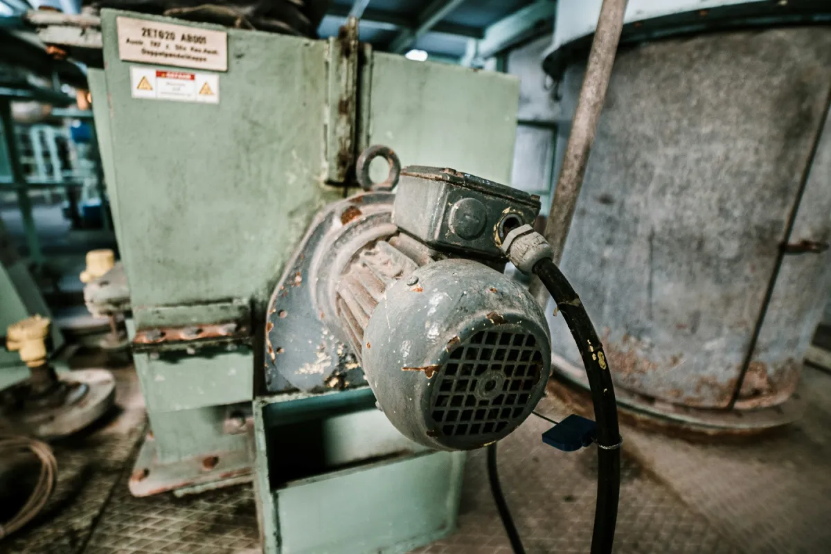
A totally enclosed fan cooled (TEFC) motor, the most common type in plants, depends entirely on the fan at the end of the shaft and the fins along the frame. Anything that disturbs that airflow raises temperature directly, even if the motor current does not change at all.
- Blocked fan cover. Plastic bags, rags, fiber, or dust caught in the fan cover grille reduce airflow. A fan that is broken or has come loose from the shaft removes almost all of the cooling.
- Dust and dirt on the fins. A layer of dust, product powder, or oil mixed with dust acts as a blanket over the frame fins. In feed mills, cement plants, or textile mills this layer can build up within weeks.
- High ambient temperature. Motor ratings refer to cooling air up to 40 °C[3]. An enclosed compressor room, a motor next to an oven or boiler, and a metal roof in the sun can push the air around the motor past that reference.
- Poor ventilation. A motor installed too close to a wall, inside an acoustic enclosure, or in a cramped space breathes its own hot air back in.
- Wrong duty type. A motor chosen for continuous S1 duty and then used for duty with repeated starts and stops, or the other way round, works outside its designer’s thermal assumptions[3].
Summary of why an electric motor runs hot, and how to check
The table below summarizes the causes above together with the signs that usually accompany them. These signs are first clues, not a diagnosis; several causes often appear together, for example a loose connection that also unbalances the voltage.
| Cause | Common signs | How to check | First action |
|---|---|---|---|
| Overload | Current on all three phases balanced but above rated; whole frame evenly hot | Measure current on each phase and compare with the nameplate | Check the driven load and its operating point; review motor sizing |
| Voltage unbalance | Phase currents differ widely; one phase runs hotter | Measure the three line-to-line voltages under load and calculate the unbalance | Trace the source in the panel and network; reduce load if above 1% |
| Voltage too low or too high | Current rises at the same load; motor slow to reach speed | Measure voltage at the motor terminals, not only at the transformer | Check cable size, transformer tap, and voltage drop during starting |
| Loss of one phase | Humming, zero current on one phase, motor will not start | Measure current and voltage on all three phases; check fuses and contactor | Stop the motor at once; replace the blown or worn component |
| Harmonics and drives | Hot at low speed; current looks normal | Record drive output frequency and temperature at several speeds | Check the manufacturer’s derating curve; consider a separate fan |
| Too many starts | Trips after several starts close together | Count starts per hour from the control log | Adjust the control logic or select a suitable motor and starter |
| Bearings | One end hotter; noise or vibration has changed | Compare DE and NDE temperatures; measure vibration | Check lubrication; schedule bearing replacement |
| Misalignment | Coupling-end bearing hotter; coupling wears fast | Check shaft alignment with a dial indicator or laser | Realign to tolerance |
| Impaired cooling | Frame hot but current normal | Check fan, fan cover, fins, wall clearance, and ambient temperature | Clean; repair the fan; improve room ventilation |
Compiled from the account of stator failure causes by Bonnett and Soukup [1] and field practice in motor inspection.
How to measure: current, voltage, thermography, and trends
Current on each phase is the first measurement. A clamp meter goes around each of the three phase conductors in turn while the motor runs at normal load, and the readings are compared with the rated current (FLA) on the nameplate and with each other. A motor with a service factor above 1.0 under NEMA MG 1 may be loaded beyond its rating for a time, but with a higher temperature rise[4], so the service factor is best treated as a reserve, not everyday capacity. Current still below FLA does not automatically mean safe if the voltage is unbalanced or the cooling is impaired.
Voltage on each phase is measured line to line at the motor terminals or at the starter output with the motor under load, and the unbalance is calculated with the formula above. Measuring only at the transformer or main panel can hide voltage drop in cables and connections.
Thermography shows the heat distribution on the frame, the terminal box, and panel connections in a single image. ISO 18434-1 sets out general procedures for thermography in condition monitoring, including the importance of accounting for surface emissivity and comparing results with similar components under similar operating conditions[5]. A loose cable connection in the terminal box often stands out clearly as a hot spot, and is often a source of voltage unbalance too.
Motor current analysis, or motor current signature analysis (MCSA), reads the spectrum of the stator current. Thomson and Fenger show that broken rotor bars and air-gap eccentricity leave characteristic frequency components in the current[6]. Rotor damage of that kind can also add heat, and the current can be measured from the MCC panel without going near the motor.
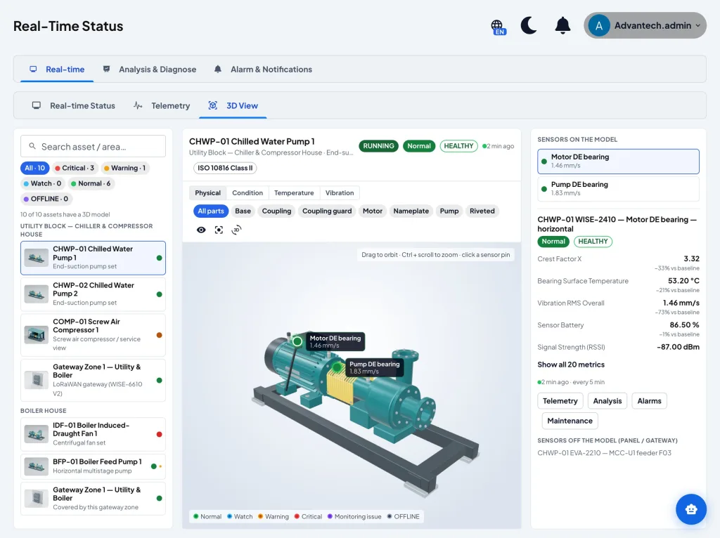
Bearing temperature trends round it all out. A single spot reading is hard to interpret, but a slow rise over several weeks at the same load and ambient is a change worth checking. These readings are most useful when stored together with current and vibration, as in a condition monitoring program that judges each machine against its own baseline.
Checking steps on the plant floor
When a motor is reported hot or has tripped, the order of the checks decides whether the cause is found or only the symptom is suppressed. The sequence below starts with safety and moves from measurements that can be taken while the motor runs to checks that need the motor stopped.
- Put safety first. Do not touch the frame of a motor suspected of running hot with a bare hand. Measurements in a live panel are taken only by authorized personnel with suitable protective equipment, and any check that touches rotating parts or terminals is done after lockout/tagout (LOTO) and verification that the energy sources are isolated.
- Record the context. When the heat started, what the load was at the time, what the ambient temperature was, and whether anything recently changed in the process, the installation, or the supply network.
- Measure line-to-line voltage under load and calculate the unbalance. Check as well whether the values fall within IEC 60034-1 zone A.
- Measure current on all three phases and compare with FLA and with each other. High balanced current points to the load; unbalanced current points to the supply or the winding.
- Check the cooling. Look at the fan cover, the fins, the clearance to walls, and the air temperature around the motor.
- Check the mechanical side. Compare DE and NDE bearing temperatures, listen to the sound, and measure vibration if an instrument is available. After LOTO, turn the shaft by hand to feel for drag and check the coupling alignment.
- Check the operating pattern. Count starts per hour and, if the motor runs on a drive, record its working speed range.
- Write the findings up as a work order with the measured figures, then repeat the same measurements after the repair to confirm the cause is really gone.
When to repair a motor and when to replace it
A motor whose winding has been damaged by heat has to be rewound or replaced. The decision is often made in a hurry because the line is down, yet its effects last for years. The U.S. Department of Energy’s motor system sourcebook advises that repair or replace decisions weigh the cost of repair against a new motor, the quality of repair practice, which can affect efficiency, and the energy cost over the motor’s remaining life[7].
That last factor depends on efficiency class. IEC 60034-30-1 groups line operated AC motors into classes IE1 (standard), IE2 (high efficiency), IE3 (premium), and IE4 (super premium)[8]. An old motor that runs nearly all year is often a reasonable candidate for replacement with a higher class, while a motor that rarely runs or has a special frame is more often worth repairing. Whichever is chosen, a new motor will fail the same way if the cause of the heat is not fixed first.
Common mistakes and limits
- Resetting the overload again and again. An overload relay that trips is doing its job. Every reset without a check adds another heat cycle to insulation that is already stressed.
- Raising the protection setting or fitting larger protection. The trips stop, but the motor loses its protection and the winding absorbs heat that should have cut the supply.
- Judging heat with the palm of the hand. A hand cannot tell a healthy frame at 60 °C from one that is getting worse, and it gives no number to compare next week.
- Measuring only one phase. Unbalance and single phasing only show up when all three phases are measured.
- Replacing the motor without finding the cause. A new motor on an unbalanced supply, with an overly heavy load, or in an unventilated room will meet the same fate.
It also needs saying plainly that temperature is a relatively slow symptom. Some faults, such as a fast-developing turn-to-turn short, can end in failure before the frame temperature changes meaningfully. Monitoring temperature, current, and vibration raises the chance of catching a problem earlier, but it does not guarantee that every failure is detected.
Conclusion
A hot electric motor is not necessarily damaged, and a motor that feels warm is not necessarily safe. The right measure is winding temperature against its insulation class, and in the field the most useful yardstick is the change in temperature against that motor’s own normal condition at similar load and ambient.
The reasons an electric motor runs hot can almost always be traced to one of three groups: electrical, mechanical, or cooling. An orderly check, starting with safety and then voltage and current on each phase, cooling, and the mechanical side, is usually enough to find it. What remains is the discipline to fix that cause rather than simply resetting the protection.
Frequently asked questions
Why does an electric motor get hot quickly?
The most common causes are overload, unbalanced three-phase voltage, voltage too low or too high, loss of one phase, too many starts, bearing problems, misalignment, and impaired cooling such as a blocked fan cover or dusty fins.
What is a normal electric motor temperature?
There is no single figure for every motor. The winding temperature limit is set by the insulation class, for example 155 °C for class F, while the frame surface is always cooler than the winding. In the field, compare the motor’s temperature with its own normal condition at similar load and ambient.
Is it normal for an electric motor to run hot?
A working motor does produce heat, and its frame can be too hot to touch. What deserves attention is a temperature higher than usual, one end hotter than the other, or a motor that trips repeatedly.
How do you calculate motor voltage unbalance?
Measure the three line-to-line voltages with the motor under load, calculate their average, then divide the largest deviation from the average by that average and multiply by 100. NEMA MG 1 recommends derating above 1% and does not recommend operation above 5%.
Can I raise the overload setting so the motor stops tripping?
No. A trip is a sign that the motor is drawing too much current or running too hot. Raising the setting removes the winding’s protection; find and fix the cause first.
References
- [1]Bonnett, A. H., & Soukup, G. C. (1992). Cause and analysis of stator and rotor failures in three-phase squirrel-cage induction motors. IEEE Transactions on Industry Applications, 28(4), 921-937.
- [2]International Electrotechnical Commission. (2007). IEC 60085:2007 Electrical insulation: Thermal evaluation and designation. IEC.
- [3]International Electrotechnical Commission. (2022). IEC 60034-1:2022 Rotating electrical machines, Part 1: Rating and performance. IEC.
- [4]National Electrical Manufacturers Association. (2021). NEMA MG 1-2021 Motors and generators. NEMA.
- [5]International Organization for Standardization. (2008). ISO 18434-1:2008 Condition monitoring and diagnostics of machines: Thermography, Part 1: General procedures. ISO.
- [6]Thomson, W. T., & Fenger, M. (2001). Current signature analysis to detect induction motor faults. IEEE Industry Applications Magazine, 7(4), 26-34.
- [7]U.S. Department of Energy. (2014). Improving motor and drive system performance: A sourcebook for industry. U.S. Department of Energy, Advanced Manufacturing Office.
- [8]International Electrotechnical Commission. (2014). IEC 60034-30-1:2014 Rotating electrical machines, Part 30-1: Efficiency classes of line operated AC motors (IE code). IEC.