
Asset reliability
Electric motor vibration standards: ISO 10816, ISO 20816, and how to read them
A technician holds a meter against the bearing housing of a pump motor, and the display reads 3.1. That number only means something once three questions are answered: 3.1 in what unit, measured how, and compared with which limit. This article covers the standard that answers the last question, and the measuring habits that keep the first two from misleading you.
Key takeaways
- The most widely cited electric motor vibration standard is the ISO 10816 series, now replaced by the ISO 20816 series; for motors above 15 kW, the relevant part is ISO 20816-3.
- Severity is usually judged from vibration velocity in mm/s RMS on the bearing housings, over a broad frequency band such as 10 to 1,000 Hz.
- The boundaries of zones A, B, C, and D depend on the machine power group and the stiffness of its foundation, so the same number can mean "acceptable" on one motor and "needs action" on another.
- Change against the motor's own baseline is often more meaningful than the absolute zone, provided the point, direction, and load condition of the measurement are always the same.
What an electric motor vibration standard is
On the shop floor, an electric motor vibration standard usually means the vibration limit used to decide whether a motor is still fit to run. The source of that limit is almost always the same: the ISO series on evaluating machine vibration, formerly numbered ISO 10816 and now ISO 20816. The standard is not written specifically for electric motors. It applies to industrial machines in general, including motors, pumps, fans, and compressors, and a motor is judged as part of a machine group according to its power and its support[1][2].
The standard covers three things. First, what is measured: the quantity, the type of value, and the frequency range. Second, where and how to measure it. Third, how to judge the result, through evaluation zones and a criterion for change[1]. The three are linked. The zone limits only apply when the measurement is taken the way the same standard specifies. A number from a meter that measures a different quantity, or one taken at a different point, cannot be compared directly with its table.
This article focuses on the standard and how to use it on motors. The broader basics of vibration analysis, such as the FFT spectrum and common fault patterns, are covered in the article on machine vibration analysis.
Motor vibration units: displacement, velocity, and acceleration
Motor vibration can be expressed in three quantities. Displacement is measured in micrometers (µm) and states how far a surface moves from its rest position. Velocity is measured in millimeters per second (mm/s) and states how fast that surface moves. Acceleration is measured in m/s² or in units of g, where 1 g equals standard gravity, about 9.81 m/s².
To judge overall severity on the bearing housings, the standard uses velocity RMS in mm/s, measured over a broad frequency band[1]. For industrial machines within the scope of ISO 10816-3, that band is generally 10 to 1,000 Hz, with its lower limit reduced for low-speed machines[3]. The reason is practical. Across the frequency range where most of the mechanical forces in a motor sit, a single velocity limit can be used over a wide range of speeds. Randall notes that for machine vibration, velocity spectra tend to be the flattest of the three quantities[4], so the overall value is not dominated by one end of the spectrum.
The other two quantities still have their place. Displacement is more sensitive at low frequencies and is used, for example, to measure shaft motion relative to a sleeve bearing on large machines. Acceleration is more sensitive at high frequencies, so it is used to look for early signs of rolling bearing damage that do not yet show up in velocity[5].
Besides the quantity, the type of value must also match. The same vibration signal can be stated as a peak value, a peak to peak value, or an RMS (root mean square) value. The zone tables use RMS. For pure sinusoidal vibration, the relationship between RMS and peak is fixed.
RMS and peak value for sinusoidal vibration
v(RMS) = v(peak) ÷ √2 ≈ 0.707 × v(peak)
v(peak) = velocity amplitude from zero to peak; the peak to peak value is twice this.
This relationship is exact only for a single sinusoid. Real motor vibration is a mix of many frequencies, so its peak to RMS ratio can differ from √2 and a conversion with the 0.707 factor is only an estimate.
From ISO 10816 to ISO 20816
For many years, the main reference for motor vibration limits was the ISO 10816 series, which evaluates vibration from measurements on the non-rotating parts of a machine. ISO 10816-1 contains the general guidelines[6], while ISO 10816-3 gives limits for industrial machines with nominal power above 15 kW and nominal speeds of 120 to 15,000 r/min, measured in situ[3]. Many meter manuals, internal plant procedures, and tables on the internet still quote these documents.
That series has been replaced. ISO 20816-1:2016 replaces ISO 10816-1 and combines it with the guidance for measurements on rotating shafts, which previously sat in a separate series, ISO 7919[1]. ISO 20816-3:2022 replaces ISO 10816-3 for industrial machines above 15 kW, with the speed range extended to 30,000 r/min[2]. The evaluation framework is still easy to recognize: velocity RMS on the bearing housings, four evaluation zones, and a distinction by machine size and by stiffness of support.
| Former document | Scope | Replacement |
|---|---|---|
| ISO 10816-1:1995 | General guidelines for evaluating vibration from measurements on non-rotating parts | ISO 20816-1:2016, which also covers measurements on rotating shafts |
| ISO 10816-3:2009 | Industrial machines above 15 kW, 120 to 15,000 r/min, measured in situ | ISO 20816-3:2022, industrial machines above 15 kW, 120 to 30,000 r/min |
Summarized from ISO 10816-1 [6], ISO 10816-3 [3], ISO 20816-1 [1], and ISO 20816-3 [2]. Check the ISO catalog for the status of the latest edition before setting a reference.
The implication is simple. A plant procedure that still cites ISO 10816-3 is not automatically wrong, because the underlying concepts are the same. But the reference document should be updated to the current edition, and every limit in use should be checked against that edition rather than copied from an old table.
Evaluation zones A, B, C, and D
The core of the standard is four evaluation zones. Every reading is placed in one of the zones, and each zone has a meaning defined in the standard[1]. That meaning is what should drive the action, not the green or red color on the meter display.
- Zone A. Vibration typical of newly commissioned machines. A motor in this zone needs no action, but the reading is worth recording as a baseline.
- Zone B. Normally considered acceptable for unrestricted long-term operation. The right action is to keep trending at the agreed interval.
- Zone C. Normally considered unsatisfactory for long-term continuous operation. The motor may generally run for a limited period until a suitable opportunity arises for remedial action. This is where planning starts: the measurement interval is tightened, the cause is investigated, and the repair is scheduled for the next planned stop.
- Zone D. Vibration at this level is normally considered severe enough to cause damage to the machine. The decision to stop the motor needs to be discussed with production right away, with attention to safety and the consequences of failure.
The A/B boundary is often misread as a target every older motor must reach. Many motors that have run for years sit in zone B and, by definition, remain fit for long-term operation. The standard also states that the zone boundaries are not intended as acceptance specifications; acceptance criteria for new machines are a matter of agreement between supplier and purchaser[3].
Machine groups, foundation types, and the limit table
The numeric zone boundaries are not the same for every motor. ISO 10816-3 divides machines into two groups by size. Group 1 covers large machines with rated power above 300 kW, including electrical machines with a shaft height of 315 mm or more. Group 2 covers medium-size machines with rated power above 15 kW up to 300 kW, including electrical machines with a shaft height from 160 mm to below 315 mm[3]. Shaft height is the distance from the mounting surface of the motor feet to the shaft centerline, and on IEC motors it is usually reflected in the frame size number.
The second distinction is support flexibility. A support is considered rigid in a given direction when the lowest natural frequency of the combined machine and support in that direction is at least 25 percent higher than the main excitation frequency, which for most machines is the rotational frequency. All other supports are considered flexible[3]. So rigid or flexible is not only a matter of foundation material. The same motor can be rigid vertically and flexible horizontally, and a motor on a light steel frame can fall in the flexible category even though the frame looks sturdy.
The table below shows the velocity RMS zone boundaries from the 2009 edition of ISO 10816-3. They are shown because they still appear often in plant procedures and meters, and to make visible how much the machine group and foundation change the evaluation.
| Machine group | Foundation type | A/B boundary | B/C boundary | C/D boundary |
|---|---|---|---|---|
| Group 2 (above 15 up to 300 kW) | Rigid | 1.4 | 2.8 | 4.5 |
| Group 2 (above 15 up to 300 kW) | Flexible | 2.3 | 4.5 | 7.1 |
| Group 1 (above 300 kW) | Rigid | 2.3 | 4.5 | 7.1 |
| Group 1 (above 300 kW) | Flexible | 3.5 | 7.1 | 11.0 |
Values from ISO 10816-3:2009 Annex A [3]. ISO 20816-3:2022 has revised this document [2]; check the current edition and your machine class before using these numbers as limits. The standard also gives displacement limits, which are not reproduced here.
Note that one value can fall into different zones. A vibration of 4.0 mm/s RMS is in zone C for a Group 2 motor on a rigid foundation, but in zone B for a Group 1 motor on a rigid foundation or a Group 2 motor on a flexible foundation. That is why each motor needs its group and foundation type decided first and recorded in the asset data, before any meter reading is interpreted.
For small motors rated 15 kW or less, ISO 10816-3 does not apply. ISO 10816-1 used to provide a separate general class table, including one for small machines[6]. The numbers from that table are not quoted here; refer to the part of the standard that applies to your type of machine. On small motors, the trend against baseline is often the most useful evaluation tool.
The scope of the standard also needs checking before the table is used. ISO 10816-3, for example, does not cover machines coupled to reciprocating machinery[3], because reciprocating machines produce vibration of a different character and are evaluated under a separate part of the standard.
How to measure electric motor vibration
Measurement points, directions, and operating conditions
Measurements for zone evaluation are taken on non-rotating parts, namely the bearing housings or rigid structure close to them[1]. On a horizontal motor, that means two locations: the drive end (DE) near the coupling, and the non-drive end (NDE) near the cooling fan. The fan cover, the terminal box lid, and the frame fins are poor measurement points, because those thin parts have vibration of their own.
The standard calls for radial measurements in two mutually perpendicular directions, and axial measurements mainly at bearing locations that carry axial load[3]. On routes, many plants measure all three directions, horizontal (H), vertical (V), and axial (A), at both bearings, so one motor yields six data points. High axial vibration, for example, is often an early sign of misalignment between the motor and the pump it drives[5].
Operating condition matters as much as location. Measurements are taken with the machine running at steady state at its normal operating speed and load, after the rotor and bearing temperatures have stabilized[3]. A pump motor measured with the discharge valve almost closed, or a conveyor motor measured while running empty, produces a number that cannot be compared with the table or with last month's reading.
Finally, measure at the same point every time. Mark each location permanently, for example with a small bonded metal mounting pad, and give it a clear name such as "P-101 motor DE H". Moving a few centimeters from one visit to the next can change the result noticeably, and that change is easily read as a change in the motor's condition.
Portable meters and permanently mounted motor vibration sensors
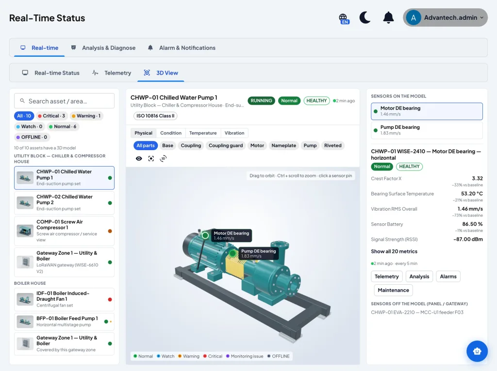
There are two main ways to collect data. Portable instruments, from a simple vibration meter that shows a single number to a data collector that records spectra, are carried by a technician along a machine route at regular intervals[5]. Permanently mounted vibration sensors, now often battery-powered wireless units bolted to the bearing housing, send readings periodically without a visit. ISO 13373-1 distinguishes permanent and periodic monitoring of this kind, and describes transducer selection and mounting[7].
The choice between them depends on how critical the motor is and how fast the faults you want to catch develop. Portable instruments are cheap per point, but they only capture the condition on the day of the visit, so a fault that develops between two routes can be missed. Mounted sensors give a dense trend and always measure at the same point and direction, which is exactly what a good trend requires. The drawback is that many wireless sensors limit the sampling rate and record length to save battery, so in-depth diagnosis still calls for more detailed measurement. Mounting also matters: a sensor bolted to a flat surface transmits high frequencies better than a magnetic sensor sitting on a thick layer of paint[7].
Trend, baseline, and alarm limits
Why the trend often matters more than the zone
Zones give the same outer fence to every motor in a group. Yet motors of the same type can have different normal vibration levels, because their foundations, piping, couplings, and repair histories differ. ISO 20816-1 therefore uses two evaluation criteria: the vibration magnitude against the zone boundaries, and the change in vibration magnitude against the machine's own reference value. A significant change can call for action even though zone C has not been reached[1].
Alarm and trip limits
For day-to-day operation, the standard uses two operational limits. An alarm warns that vibration has reached a defined value or has changed significantly, so remedial action may be needed; the machine can generally keep running while the cause is investigated. A trip is the vibration magnitude beyond which further operation may damage the machine, so immediate action is needed to reduce the vibration or stop the machine[1].
Alarm values should be set for each machine, relative to a baseline established from experience at that machine's measurement point, and generally not far above the upper limit of zone B. Trip values relate to the mechanical integrity of the machine and generally lie in zone C or D[3]. On motors wired into a protection system, an automatic trip decision also needs to weigh the risk of stopping the process suddenly, for example on a cooling water pump serving a chiller.
Example: reading a pump motor vibration measurement
The numbers below are illustrative, not data from a particular plant. A 75 kW motor drives a cooling water pump at 2,970 r/min and sits on a concrete foundation that has been assessed as rigid. Its power lies between 15 and 300 kW, so the motor is in Group 2, and the limits from Table 2 are 1.4, 2.8, and 4.5 mm/s RMS. The readings are taken with the pump running at its normal flow.
| Measurement point | Horizontal (H) | Vertical (V) | Axial (A) |
|---|---|---|---|
| Drive end (DE), today | 3.1 | 2.2 | 1.6 |
| Non-drive end (NDE), today | 2.4 | 1.9 | 1.2 |
| Drive end (DE), baseline | 1.8 | 1.7 | 1.4 |
Illustrative data for the worked example.
The first step is to take the highest value across all points and directions, 3.1 mm/s RMS at DE horizontal. That is above the B/C boundary (2.8) and has not reached the C/D boundary (4.5), so the motor is in zone C: it may keep running for a limited period, but a repair needs to be planned.
The second step is to compare with the baseline. At the same point, vibration rose from 1.8 to 3.1 mm/s RMS, an increase of 1.3 mm/s or about 72 percent (1.3 ÷ 1.8 = 0.722). The largest rise is in the horizontal direction, while the axial direction rose only slightly, from 1.4 to 1.6. A pattern like this is a pointer to start looking for the cause in the spectrum, for example unbalance or looseness, not a conclusion in itself.
The third step is to check the assumptions. If the same motor actually sat on a flexible steel frame, the limits would be 2.3, 4.5, and 7.1 mm/s RMS, and 3.1 mm/s RMS would fall in zone B. If the 3.1 that was recorded turned out to be a peak value from a meter set to peak mode, its RMS value, assuming a near-sinusoidal signal, would be only about 3.1 × 0.707 ≈ 2.2 mm/s, which is also in zone B. The same number on the display can lead to different conclusions, depending on the foundation and the type of value used.
Steps to apply the vibration standard to motors in a plant
- List the motors and set their class. Record the power, speed, shaft height, and support type of each motor, then decide the machine group and foundation category (rigid or flexible) to use.
- Set the reference document. Write down the edition of the standard in use, for example ISO 20816-3:2022, and make sure the limit table in the procedure matches that edition.
- Mark the measurement points. Define the DE and NDE points with their H, V, and A directions, mark them permanently, and name them consistently.
- Standardize the instrument settings. Make sure the meter or sensor shows velocity RMS in mm/s over the appropriate frequency range, not a peak value or a different quantity.
- Take a baseline under normal conditions. Measure while the motor runs at its usual load and speed with stable temperatures, and repeat after every major repair.
- Set alarm and trip limits per motor. Start from the zones as an outer fence, then adjust the alarm to each motor's baseline.
- Connect results to action. Every motor that enters zone C or changes significantly needs a clear work order in the CMMS, then a verification measurement after the repair.
Common mistakes when reading motor vibration
- Comparing peak values with an RMS table. A meter set to peak or peak to peak shows a larger number than RMS for the same vibration. Comparing it directly with the zone table makes the motor look worse than it is.
- Measuring at a different point each time. A point that wanders from the bearing housing to the fan cover, or directions that get swapped, make the trend unreadable.
- Measuring with the motor unloaded or not yet stable. A motor that has just started, or a pump running with its valve almost closed, does not represent the normal operating condition on which the standard's evaluation is based[3].
- Using the wrong row of the table. Rigid foundation limits applied to a motor on a flexible frame, Group 1 limits applied to a 45 kW motor, or the industrial machine table applied to a machine outside its scope.
- Treating zone B as healthy without looking at the trend. Motor vibration can change quickly inside zone B. The criterion for change against the reference value exists precisely to catch this[1].
- Expecting vibration to catch every fault. Not every motor failure mode changes vibration clearly, some winding insulation faults for example, and a fast-developing fault can occur between two measurements. Vibration is strongest when combined with other techniques such as temperature and motor current[5].
Conclusion
An electric motor vibration standard is not a single number but a way of working. The ISO 20816 series, successor to ISO 10816, sets the quantity to measure (velocity RMS in mm/s), where to measure it (the bearing housings, in defined directions), and how to judge it (zones A to D by machine group and foundation stiffness, plus a criterion for change against the reference value).
A meter reading only means something when all of those conditions are met. Plants that get value from the standard usually set each motor's class once, measure the same way every time, read the trend against the motor's own baseline, and turn every finding into a verified action. The habit can start on a few of the most critical pump and compressor motors, then extend across the plant.
Frequently asked questions
Which electric motor vibration standard is used in industry?
The most common reference is the ISO 10816 series, now replaced by the ISO 20816 series. For motors and industrial machines above 15 kW, the relevant part is ISO 20816-3:2022, the successor to ISO 10816-3:2009.
What unit is used for motor vibration?
To judge severity, the usual unit is velocity in mm/s RMS. Displacement is stated in µm and acceleration in m/s² or g; both are used for other purposes, such as low-speed machines and early-stage bearing damage.
What is the allowable vibration limit for an electric motor?
It depends on the machine group and the foundation. Under ISO 10816-3:2009, a motor above 15 up to 300 kW on a rigid foundation enters zone C above 2.8 mm/s RMS and zone D above 4.5 mm/s RMS; check the current edition of ISO 20816-3 before using these numbers.
How do you measure pump motor vibration?
Measure on the drive-end and non-drive-end bearing housings in the horizontal, vertical, and axial directions, with the pump running at normal load and temperatures stable. Use the same points every time so the trend can be compared.
Does a motor need a permanently mounted vibration sensor?
Not always. A portable meter is enough for many motors, while a mounted sensor suits critical or hard-to-reach motors better, because it gives a dense trend and always measures at the same point.
References
- [1]International Organization for Standardization. (2016). ISO 20816-1:2016 Mechanical vibration: Measurement and evaluation of machine vibration, Part 1: General guidelines. ISO.
- [2]International Organization for Standardization. (2022). ISO 20816-3:2022 Mechanical vibration: Measurement and evaluation of machine vibration, Part 3: Industrial machinery with a power rating above 15 kW and operating speeds between 120 r/min and 30 000 r/min. ISO.
- [3]International Organization for Standardization. (2009). ISO 10816-3:2009 Mechanical vibration: Evaluation of machine vibration by measurements on non-rotating parts, Part 3: Industrial machines with nominal power above 15 kW and nominal speeds between 120 r/min and 15 000 r/min when measured in situ. ISO.
- [4]Randall, R. B. (2011). Vibration-based condition monitoring: Industrial, aerospace and automotive applications. Wiley.
- [5]Mobley, R. K. (2002). An introduction to predictive maintenance (2nd ed.). Butterworth-Heinemann.
- [6]International Organization for Standardization. (1995). ISO 10816-1:1995 Mechanical vibration: Evaluation of machine vibration by measurements on non-rotating parts, Part 1: General guidelines. ISO.
- [7]International Organization for Standardization. (2002). ISO 13373-1:2002 Condition monitoring and diagnostics of machines: Vibration condition monitoring, Part 1: General procedures. ISO.